303-232-4100
About MSEC, Inc.
Our Leadership
MSEC Line Card
Manufacturers
Career Opportunities
Blog
Control Valves
Cooling Towers
Heat Transfer
Industrial Valves
Instrumentation
Pressure Protection
Severe Service Valves
Steam Specialties
Valve Automation
Tips and Tools
Request a Quote
Menu
Our Products
Industrial Valves
Gate, Globe, Check, Butterfly and Ball Valves
API-6A and API-6D Industrial Valves
Shut Off Pig Valves
Pressure Seal Valves
Ready to Get Started?
Contact Us
Control Valves
2 and 3-way Globe Valves
Pneumatic Actuators
Remanufactured (Fisher, Orbit, Norriseal) Valves
Steam Control Valves
Ready to Get Started?
Contact Us
Instrumentation
Arctic Rated Pressure & Temperature Switches
Ready to Get Started?
Contact Us
Pressure Protection Valves and Regulators
Safety and Relief Valves
Ready to Get Started?
Contact Us
Valve Automation
Pneumatic Quarter-Turn and Linear Valve Automation
Electric Multi-Turn, Quarter-Turn and Linear Actuators
Positioners, Switches & Transmitters
Ready to Get Started?
Contact Us
Severe Service Valves
Steam Specialties
Condensate and BFW Pumps
Desuperheaters and Steam Attemperators
Ready to Get Started?
Contact Us
Heat Transfer Equipment
Corrosion Free Packaged Cooling Towers
Ready to Get Started?
Contact Us
Pipeline Auxiliaries
Tee and Temporary Strainers
Services
Shop Services
Applications
About MSEC, Inc.
Our Leadership
MSEC Line Card
Manufacturers
Career Opportunities
Blog
Control Valves
Cooling Towers
Heat Transfer
Industrial Valves
Instrumentation
Pressure Protection
Severe Service Valves
Steam Specialties
Valve Automation
Tips and Tools
Request a Quote
Customer Portal
Ready to Get Started?
Contact Us
303-232-4100
Contact Us
Menu
Request a Quote
Menu
Our Products
Industrial Valves
Gate, Globe, Check, Butterfly and Ball Valves
API-6A and API-6D Industrial Valves
Shut Off Pig Valves
Pressure Seal Valves
Ready to Get Started?
Contact Us
Control Valves
2 and 3-way Globe Valves
Pneumatic Actuators
Remanufactured (Fisher, Orbit, Norriseal) Valves
Steam Control Valves
Ready to Get Started?
Contact Us
Instrumentation
Arctic Rated Pressure & Temperature Switches
Ready to Get Started?
Contact Us
Pressure Protection Valves and Regulators
Safety and Relief Valves
Ready to Get Started?
Contact Us
Valve Automation
Pneumatic Quarter-Turn and Linear Valve Automation
Electric Multi-Turn, Quarter-Turn and Linear Actuators
Positioners, Switches & Transmitters
Ready to Get Started?
Contact Us
Severe Service Valves
Steam Specialties
Condensate and BFW Pumps
Desuperheaters and Steam Attemperators
Ready to Get Started?
Contact Us
Heat Transfer Equipment
Corrosion Free Packaged Cooling Towers
Ready to Get Started?
Contact Us
Pipeline Auxiliaries
Tee and Temporary Strainers
Services
Shop Services
Applications
About MSEC, Inc.
Our Leadership
MSEC Line Card
Manufacturers
Career Opportunities
Blog
Control Valves
Cooling Towers
Heat Transfer
Industrial Valves
Instrumentation
Pressure Protection
Severe Service Valves
Steam Specialties
Valve Automation
Tips and Tools
Request a Quote
Customer Portal
Ready to Get Started?
Contact Us
Contact Us
Call Us
Menu
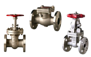
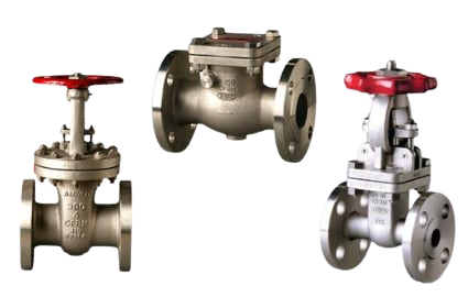
MSEC-Aloyco-2.png (1)
Author :
Pat Bryant
|
Date : March 19, 2024
|
Categories: