- Contact Us
- Call Us
- Menu
High performance butterfly valves (HPBV) are a standard in many industries including heating, ventilating and air conditioning, power generation, hydrocarbon processing, water and waste water treatment, and marine and commercial shipbuilding.
They are also installed in applications as diverse as food and beverage processing, snowmaking and pulp and paper production. Configurations are available for harsh conditions as well as applications requiring nominal pressure and temperature ratings.
The following describes the soft seating design principles for high performance butterfly valves:
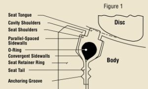 In Figure 1, the disc and seat are not engaged. In this position, the shoulders of the seat are forced against the cavity shoulders by the compression of the o-ring.
The seat is recessed inside the seat cavity and acts as a gasket in the anchoring groove area.The seat cavity is sealed from exposure from the process fluid and protects the seat from abrasion and wear. The o-ring, which is completely encapsulated by the seat, is also isolated from exposure to the process fluid.
 In Figure 2, the Flowseal disc and seat are engaged, and the process fluid is under low pressure. The edge of the disc, with a larger diameter than the seat tongue, directs movement of the seat radially outward, causing the seat to compress against the convergent sidewalls of the cavity.The elastomeric o-ring imparts a mechanical pre-load between the disc and seat tongue as it is compressed and flattened by the disc; this is the self-energized mode for sealing at vacuum-to-60 psig.
As the seat moves radially outward, the seat shoulders move away from the cavity shoulders and open the cavity to the process media.
 As line pressure increases, the process fluid enters the sidewall area and applies a load against the parallel-spaced sidewall and convergent sidewall of the seat. The seat and cavity design permits the seat to move axially to the downstream sidewall, but confines the movement and directs the movement radially inward towards the disc; the higher the line pressure, the tighter the seal between the disc and seat. Because the o-ring is elastic, it is able to flex and deform under loads and return to original shape after removal of the load; it is the rubber which deforms, not the thermoplastic material.
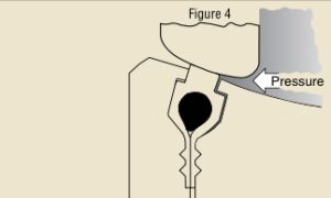 The Flowseal valve is bi-directional (in some instances, modifications may be required to operate this arrangement for dead end service). The cavity and seat sidewalls are symmetrically designed to permit, confine, and direct movement of the seat to the disc to dynamically seal with line pressure in the reverse direction. The disc edge is the segment of a sphere, and the seat is angled towards the disc edge to seal with pipeline pressure in either direction.
Recommended installation direction is “SUS” (seat upstream), as in Figure 3.