- Contact Us
- Call Us
- Menu

Most industrial applications require the monitoring of pressure and temperature of a process. Pressure and temperature measurement can be accomplished either by transmitters, gauges or by switches. This post will provide a quick introduction of industrial electromechanical pressure switches and temperature switches.
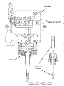
An industrial pressure and temperature switch is made up of the three main components: 1) the sensor, 2) the housing and 3) the switching element.
The correct combination of each component assures proper application of the device for its intended use.
The sensor is located above the pressure port and process connection. For pressure and differential pressure switches, there are several varieties of pressure sensors to choose. The most common types of pressure sensors are:
Metal Bellows – an accordion-like device that provides linear expansion and contraction based upon the application of pressure or vacuum. Bellows are excellent sensors because they provide good overall pressure range and are fairly sensitive to small changes in pressure.

Piston – A rod and o-ring combination that moves linearly in direct response to applied pressure. Piston sensors are normally only applied to only very high pressure ranges. They have very small surface areas and wide deadbands (the change in pressure required to change the position of the switch output).
Diaphragm – A thin, elastomer or metallic membrane, often with a rolled lip that allows for greater movement. The diaphragm has a large surface area and provides the most sensitivity to pressure change, making it ideal for low to mid-range pressure sensing.
Housings are classified and selected based on the atmosphere in which they’ll be used. Housing ratings are classified by several national and international agencies such as NEMA and CENELEC. Very generally put, housings can be rated as general purpose, dust & water resistant, water tight, corrosion resistant and hazardous (explosive) environments. Proper selection of the housing is important to the operation and life expectancy of the device. In hazardous environments, proper selection is absolutely critical. If unsure about the housing classification, consultation with an applications expert is required.
The switching element refers to the signaling device inside the enclosure that responds to the movement of the sensor. It can be either electrical or pneumatic, and provides an on-off signal (as opposed to an analog, or proportional signal produced by transmitters).
The switching element is most times a “micro” type single pole, double throw (SPDT) electrical switch. These microswitches come in many configurations and electrical ratings, such as double pole, double throw (DPDT), 120/240 VAC, 12VDC, 24VDC, and hermetically sealed.
For the switching element and the sensor, it is very important to know the cycling rate (number of on vs. off times over a period of time) the instrument will see. Since both of these elements are mechanical, they will eventually wear out and need to be replaced. Switches are an economical and strong performing choice for low to medium cycle rates. For extremely high cycle rates, the use of solid state transmitters are a better choice.

Temperature Switches
An electromechanical temperature switch (sometimes called a thermostat) is, for the most part, a piston type pressure switch connected to an oil filled capillary and bulb sensing element. The thermal expansion of the oil inside the bulb and capillary creates the pressure and linear movement upon the piston sensor of the switch. The bulb and capillary elements can be supplied in copper or stainless steel, and at various lengths.
There are many more details to selecting and applying electromechanical pressure and temperature switches. This post is only intended to provide a very general introduction. It is always suggested to discuss your application with a qualified applications engineer so that you are assured to get the longest lasting, most economical and safest instrument possible.