- Contact Us
- Call Us
- Menu
Industrial processing often requires the transfer of heat, sometimes into the process, sometimes out of the process. External heat sources are often steam, hot water, or electric heaters. There are also instances where processing machinery either adds heat to the process or requires heat removal (cooling) in order to maintain proper function. If the heat source can accommodate a flowing liquid to provide the removal of excess heat, it is a candidate for a closed-loop cooling system.
One schematic for a closed-loop cooling circuit would show the heat source connected to the piping system, with a pump for circulation and a finned coil located outdoors. The pump moves the heat transfer liquid through the hot area where heat moves from the process to the flowing liquid. The heated liquid continues to flow through the piping system to the finned coil, located outdoors. A fan moves air across the coil to provide heat transfer. The finned coil size would need to be comparatively large since only sensible cooling using forced air is employed. The fan capacity would be commensurate with the coil size and the circulating pump rating would be in line with the fluid-moving requirements of the system. While this design is fairly simple, there may be a more efficient way to accomplish the heat transfer and deliver what may be beneficial additional features.
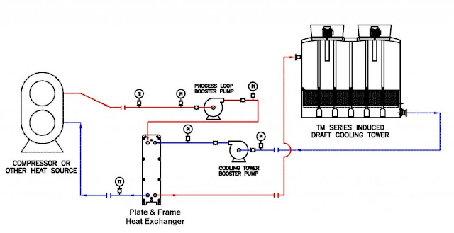
Consider a different schematic for the same application. This alternate design employs a closed-loop cooling circuit for the heat source but utilizes a different means of rejecting the heat from the closed loop to the outside air. A plate and frame heat exchanger transfers heat from the closed cooling loop to an open loop circuit that circulates through a cooling tower located outdoors. This scenario maintains the closed-loop nature of the equipment cooling circuit, preventing the entry of particulates or dissolved gases into the cooling fluid circulating through the process or machinery. Here is what the schematic looks like courtesy of Delta Cooling Towers.
The cooling tower offers far greater efficiency than the fan and coil arrangement in the first design. Employing a plastic cooling tower will drastically reduce the life cycle cost over a galvanized steel model and the cooling tower will occupy significantly less space and require a less costly support structure than the larger fan and coil arrangement. Total horsepower requirements for the system are reduced. The closed loop will not require any chemical additions for freeze protection because it no longer extends outdoors. This system also provides an element of flexibility, with the expansion of the plate and frame heat exchanger a possibility. Cooling tower capacity is also expandable and available for other uses throughout the facility. There are more details provided in the datasheet included below. Share your heat transfer and cooling challenges with application experts and explore various options. The combination of your process knowledge and experience with your product application expertise will produce an effective solution.