

The Interior West has quietly become one of the fastest-growing electricity markets in the country. Utilities across Utah, Colorado, Nevada, New Mexico, and Arizona are forecasting demand growth north of 50 percent over the next decade, and Wyoming is fielding load commitments large enough to reshape the state’s generation profile outright. Population isn’t what’s driving it. AI data center campuses are landing in the region at a scale nobody was planning for five years ago — some drawing several hundred megawatts, a few designed to eventually scale past a gigawatt.
Every one of those campuses needs firm, round-the-clock power, and developers increasingly aren’t waiting in an interconnection queue to get it. They’re building generation on-site or immediately next door. That means a wave of new combined cycle plants, simple cycle peaking units, fuel cell yards, and behind-the-meter power hubs is moving through engineering and construction right now.
It’s worth being honest about where this is happening. Several Front Range communities have paused data center development, and momentum has shifted toward Wyoming and Utah as a result. The work is real, but the map is moving.
For anyone who specifies, supplies, or services flow control equipment, this is the most significant demand shift the region has seen in a generation.
Behind-the-meter and islanded configurations avoid federal interconnection jurisdiction, which removes one major source of schedule risk. They don’t remove all of it. Air permitting for gas turbines is frequently the actual critical path, and turbine lead times are running long enough to force procurement decisions well ahead of detailed design.
The operative phrase in this market is “speed to power.” Long-lead equipment gets locked in early, and EPCs are under real pressure to avoid anything that pushes commercial operation to the right. In practice, availability tends to carry as much weight as unit price. Suppliers who can support fast turnaround, local stocking, and quick actuator mounting and configuration have an advantage that’s hard to compete away on cost alone.
A combined cycle plant is a dense valve environment, and the applications break into a few clear buckets.
Fuel gas front end. Metering and regulation skids, filter separators, and conditioning equipment feeding the gas turbines. This is where you see double block-and-bleed ball valves, triple-offset butterfly valves, and fast-acting emergency shutdown valves — usually SIL-rated, spring-return, with partial stroke testing capability so the plant can verify function without tripping the unit.
HRSG and steam cycle. Main steam isolation, drum level control across HP, IP, and LP circuits, superheater and reheater attemperator spray valves, startup vents, and continuous and intermittent blowdown. Blowdown in particular is punishing erosive service that eats standard trim. Attemperator sprays demand tight shutoff plus fine controllability, which is a harder combination than it sounds.
Turbine bypass. These are the marquee severe-service items — large steam conditioning valves handling significant pressure and temperature letdown, often with noise attenuation requirements and fast stroking demands during startup and trip events.
Feedwater and condensate. Boiler feed pump minimum flow recirculation is a classic high-pressure-drop application requiring multi-stage anti-cavitation trim. Add feedwater regulating valves, condensate control, and deaerator level.
Cooling and water treatment. In the arid West, water constraints push a lot of these plants toward air-cooled condensers and zero liquid discharge systems. That changes the mix — less large-bore circulating water, more demineralization, reverse osmosis, and chemical injection service. Expect large-diameter rubber-lined or triple-offset butterfly valves on what circ water remains, plus thermoplastic and lined valves throughout treatment trains.
Balance of plant and emissions. Instrument air, lube oil, auxiliary cooling, fire protection deluge, and SCR ammonia or urea injection skids.
Modulating service still leans heavily on pneumatic spring-diaphragm and piston actuators paired with smart digital positioners. Isolation duty, especially in remote yard locations without reliable instrument air, is trending toward electric quarter-turn and multi-turn actuators. Large fast-stroking applications — turbine bypass, main steam trip — often justify electro-hydraulic packages.
Altitude deserves more attention than it usually gets, though not where people expect. Pneumatic actuator thrust is a function of gauge pressure, which is referenced to ambient, so a spring-diaphragm actuator delivers essentially the same output at 6,000 feet as it does at sea level. The real derate sits upstream. Compressor capacity falls roughly three percent per thousand feet of elevation, and an instrument air system in Denver may need to be substantially larger than an equivalent sea-level system to deliver the same SCFM. Electric actuators derate as well, since thinner air carries less heat away from the motor. Wide ambient temperature swings drive enclosure ratings, lubricant selection, and heater requirements on top of all that.
There’s a wrinkle here that a lot of vendor content gets wrong, and it’s worth getting right because it changes what you should be specifying.
AI training workloads produce severe power swings. A large training run is synchronous: the model is split across thousands of GPUs, and every iteration alternates between a compute phase, where each GPU pulls near maximum power doing dense matrix math, and a gradient synchronization phase, where the compute units go relatively idle while results move across the interconnect. Because the GPUs run in lockstep, those phases don’t average out the way thousands of independent web workloads would. They move as one. A single rack can swing between roughly 30 and 100 percent draw, and aggregated across a data hall that becomes hundreds of megawatts shifting in milliseconds.
Here’s the part that matters: those transients never reach the steam cycle.
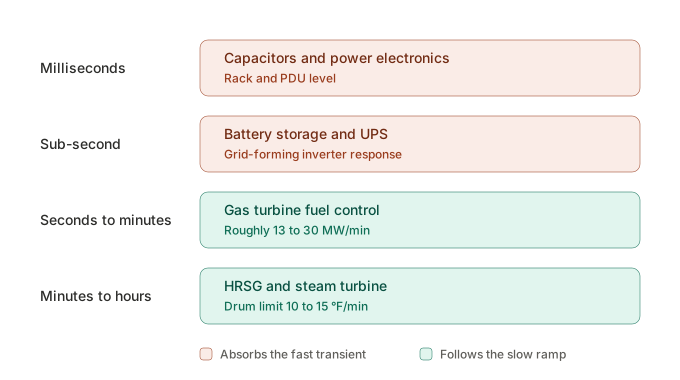
Generation responds in a hierarchy of timescales. Capacitors and power electronics act in milliseconds. Battery storage and grid-forming inverters cover the sub-second window. Gas turbine fuel control works in seconds to minutes — an F-class machine ramps somewhere around 13 to 30 MW per minute depending on where it sits on the load curve. The steam side is slower still, by a wide margin.
The constraint on the steam side is thermal stress, not control logic. Rapid pressure and temperature changes drive differential expansion in thick-walled components, so HP drum ramp rates are typically held to something like 10 to 15 °F per minute, and steam turbine rotor warming is limited to a few degrees per minute to preserve rotor life. Combustion stability adds its own limits on the gas side, since dry low-NOx combustors won’t tolerate arbitrary fuel swings without NOx and CO excursions.
The practical result is that the steam cycle behaves like a low-pass filter. A 200 MW swing lasting 50 milliseconds is invisible to it — the transient arrives and departs many times over before the thermal system could begin to respond. Storage absorbs it, which is why these campuses get batteries and supercapacitors sized for power rather than energy: very high discharge rates, short duration, enormous cycle counts.
So what does reach the plant?
Training jobs start, finish, fail, and get rescheduled. Inference load varies through the day. Halls come online in phases. That’s variation on a minutes-to-hours timescale, and the plant follows it directly. That’s the load-following duty that matters for flow control.
And it lands squarely on the valves. Attemperator sprays modulate continuously to hold steam temperature through load changes. Drum level control fights shrink-and-swell — when load rises and pressure drops, steam bubbles expand and the level reads high even as mass leaves the drum. Feedwater regulating valves work through their range instead of parking near a fixed position. Bypass systems see more action around starts.
Low cycle fatigue from thermal cycling accounts for a large share of steam turbine rotor life consumption, and the thick-walled components exposed to it include main steam valves and casings, not just the rotor. More modulation means more wear on packing, seats, and trim — and an aftermarket meaningfully larger than the original equipment scope would suggest.
That’s the practical takeaway. Specify for modulation duty, not just isolation. And smart positioners with valve signature diagnostics tend to pay for themselves quickly in a plant that ramps.